Overview
The BeagleBone Blue is a single board computer with a 1GHz Texas Instruments Sitara AM335x (single core) microprocessor together with wifi/bluetooth, IMU/barometer, power regulation and state-of-charge LEDs for a 2-cell LiPo, H-Bridges, discrete connectors for 4 DC motors+encoders and 8 servos.
Further Informationen
https://www.digikey.com/eewiki/display/linuxonarm/BeagleBone+Blue
Robot Control Library:
Using the board with our custom build image
Quick Start
A new BeagleBone Blue board comes with debian preinstalled. It can be connected to a host with a USB cable. Upon booting a heart beat application starts automatically which causes the leds to blink. We strongly suggest to flash the board with our custom built linux image. This image contains the librobotcontrol version 1.1.0 together with examples testing all the available peripherals.
The preinstalled debian image has the following features
IP address 192.168.7.2
Username:debian PW:temppwd
Beside that you have a root user with password:toor
If anything does not work with your Ethernet over USB interface, you can use the console on UART0 to query your system. For this you need a special USB-TTL-3v3 cable and an according 4-pin adapter cable. Connect it to the pins on the board as follows (Don't connect the 3V3 pin!):
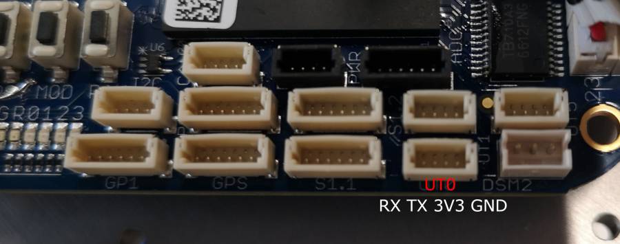

NOTE: TX and RX are labelled from the perspective of the UART Cable! Connect the cable/adapter's RX to the pin labelled TX (Pin 4) and the adapter's TX to RX (Pin 3).
Please also note that you need to power the BeagleBone Blue device by using the generic 5V USB port or the 12V power port. Beware that the board can only drive motors when powered with 12V!
You can then connect to the BeagleBone Blue device via serial console (e.g. PuTTY) with a baudrate of 115200.
Connectors and Schematics
The following figure shows the available connectors on the board.
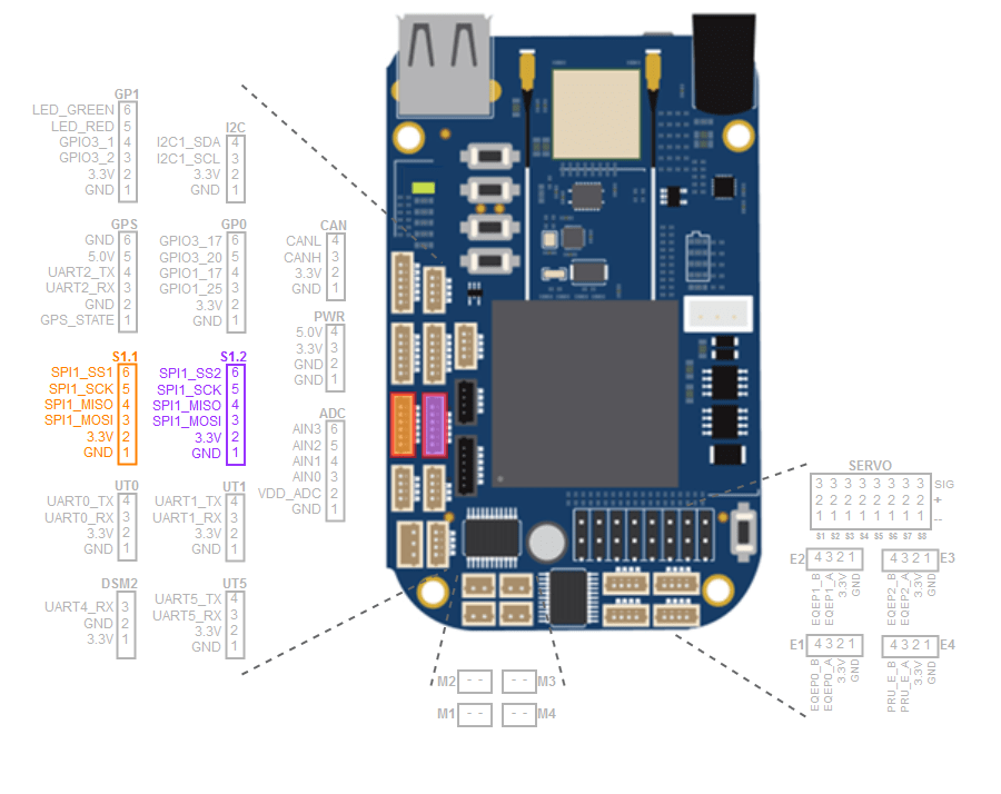
Detailed electrical information about the board can be found in the schematic. Pin numbering and multiplexed functions are described in https://github.com/beagleboard/beaglebone-blue/blob/master/BeagleBone_Blue_Pin_Table.csv
WiFi
When connecting to a WiFi, always make sure that both physical antennas are aligned correctly away from the board as follows:

To use wifi enter your WiFi's SSID and Password in /etc/wpa_supplicant.conf:
ctrl_interface=/var/run/wpa_supplicant
ctrl_interface_group=0
update_config=1

network={
        key_mgmt=WPA-PSK
        ssid="MyWifi"
        psk="MyPassword"
}
Then either reboot or restart wpa_supplicant and systemd-networkd
# restart services
systemctl restart wpa_supplicant
systemctl restart systemd-networkd
# check ip address
sudo /sbin/ip a
Troubleshooting
Using the Beagle Bone Blue attached via USB onto a Windows host may cause the device not being recognized correcty as a RNDIS network device, instead it may show up as a default serial COM device or as a unknown RNDIS device with a missing driver as follows:
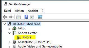
This is a known issue and caused by the wrong driver being taken by the OS or simply by missing the driver. Either way, to prevent this behaviour, the following driver for the according device has to be changed manually by downloading, unpacking and installing it via Windows Device Manager:
RNDIS driver
librobotcontrol and reading sensors
librobotcontrol has been broken on newer kernels for a while. However almost all peripherals that needed librobotcontrol are now supported natively in the kernel.
| BBlue device | Subsystem | path |
|---|---|---|
| encoders | Counter | /sys/bus/counter/devices/counterX/count0 |
| motors | PWM | /sys/class/pwm/pwmchipX |
| ADC, MPU9250, BMP280 | IIO | /sys/bus/iio/devices/iio:deviceX |
| SPI | spidev | ?? |
| PRU* (see below) | remoteproc* | /sys/class/remoteproc/remteproc[1/2] |
* This only concerns controlling the PRU itself (firmware loading, booting,...). Not what the PRU program does (e.g. encoder 4 & the servo PWM). That needs a separate driver building on remoteproc, see below.
Using PRU provided peripherals
The only functionality that doesn't work "out of the box" with an unmodified beaglebone kernel are the functions provided by the PRUs using the librobotcontrol firmware. To address that we wrote a compatibility driver as an out-of-tree module that exposes those functions in their respective subsystems.
Encoder 4 (managed by PRU0) shows up as a counter (usually counter0), while the 8 servo channels are accessible through an 8 channel PWM chip (usually pwmchip6).
PRU firmware
The firmware for the PRUs is still provided by librobotcontrol, which (for now) is still in the image. In the future we may have a separate linux-firmware-librobotcontrol package that only provides the firmware binaries.
Using the Encoders
The encoders can be read from sysfs read sys/bus/counter/devices/counterX/count0. The encoder can be set to an arbitrary value by writing to the count. Note that Encoder 4 (controlled by the PRU) currently only supports reading.
Using PWM
The PWM interface is somewhat similar to the old (v1) GPIO interface, in that a PWM pin needs to be exported before it can be used. Other than GPIOv1 however, PWM pins are not numbered globally but are local to the pwmchip.
The on/high time in nanoseconds can be set by writing to /sys/class/pwm/pwmchipX/pwmY/dutycycle.
To set the period, write the time (in nanoseconds) to /sys/class/pwm/pwmchipX/pwmY/period. Note that the servo channels do not currently support this and are fix at 10ms (100Hz).
Finally, the PWM channel can be enabled or disabled by writing 1 or 0 to /sys/class/pwm/pwmchipX/pwmY/enable.
For example, to set Servo channel 3 to a pulse width of 1ms:
echo 3 > /sys/class/pwm/pwmchip6/export
echo 1000000 > /sys/class/pwm/pwmchip6/pwm3/duty_cycle
echo 1 > /sys/class/pwm/pwmchip6/pwm3/enable